The two scientists who were to use the equipment were Dr. William B. Glendinning and Dr. Albert Mark. I remember that they met me when I arrived and they assisted me with things I needed. Al drove me around town and took me to lunch and invited me to his home to visit and Bill took care of getting the tickets for my flight home.
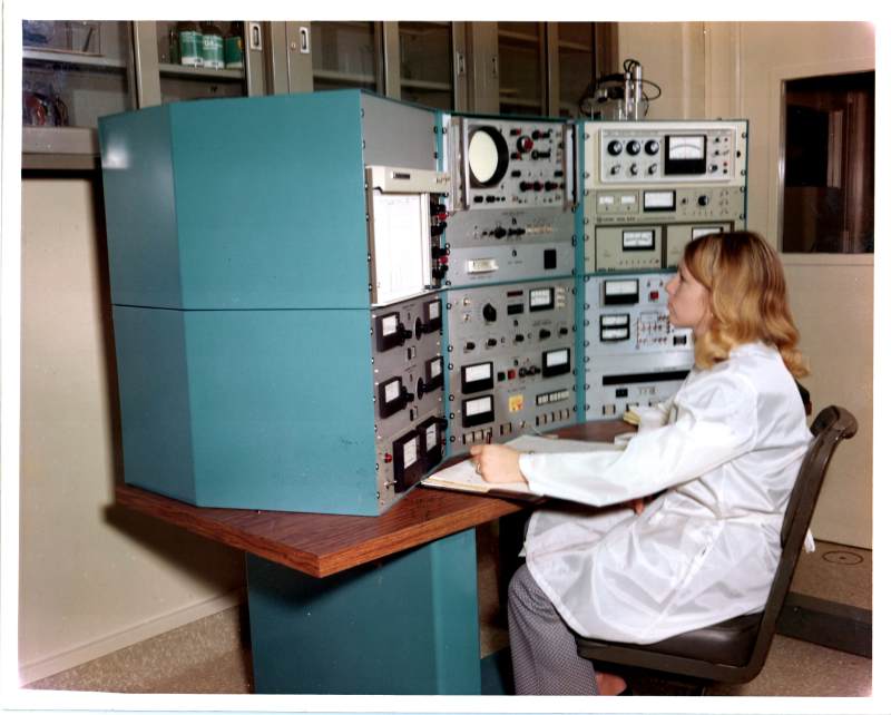
One of the scientists, Al Mark, had these pictures taken for me. I don't know who the lady was – I never met her and I don't think I ever knew her name. I also don't know why there are a mix of color and black and white photographs. (I was told this was the lab that had been used by Julius and Ethel Rosenberg in the forties and early fifties when they were convicted of espionage and executed for giving atomic secrets to the Russians.)
I've forgotten so much. On the photo of the accelerator tube and ion source can be seen the metal grounding plate I had made travelling from under the power supply and fastened to the terminal base plate. It doesn't show in the black and white photograph, but Al had it gold plated. At the bottom of the base plate is a lead cover for the cable entrance – but what is the white pipe for? I don't recall the lead-lined high voltage enclosure having windows, but it apparently did. They had built the high-voltage enclosure before I got there, but I'm puzzled why I can see bare plywood inside the enclosure – all enclosures I remember had the lead on the inside.
These are 8x10 photographs. If anyone wants a larger copy, email me at "webmaster" at this domain (tomcloud.org) or use the contact form.


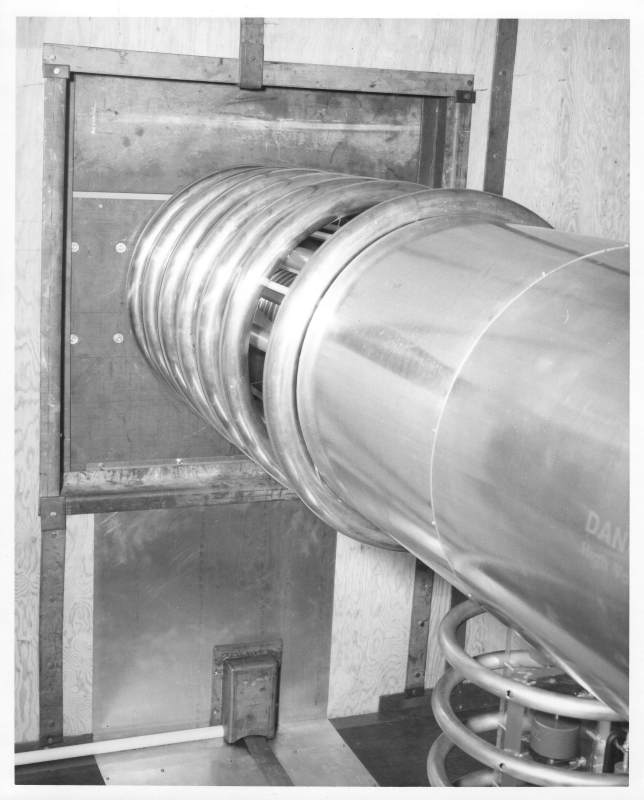
the end plate at rear and the accelerator tube
with the ion source in the metal tube
and the power supply below it.
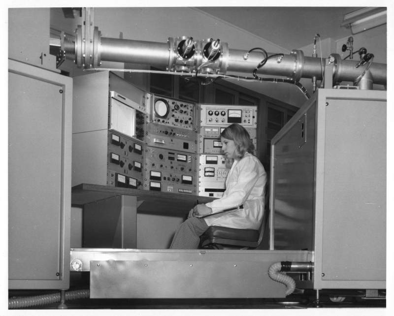
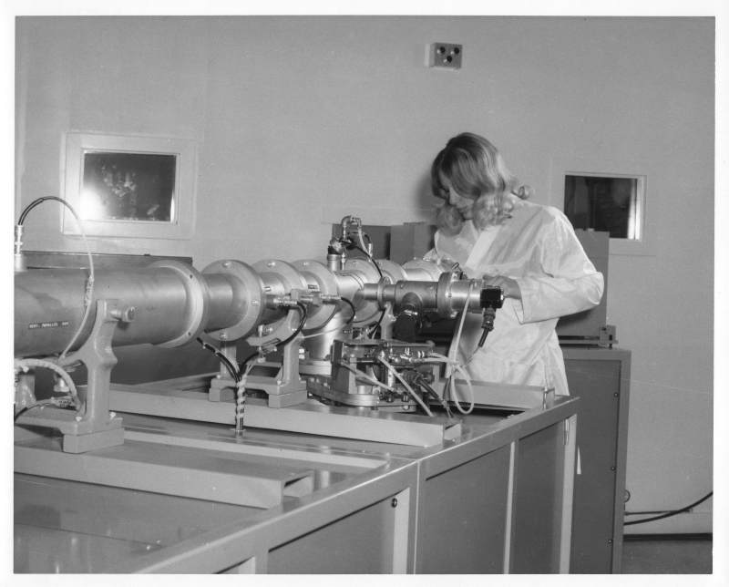
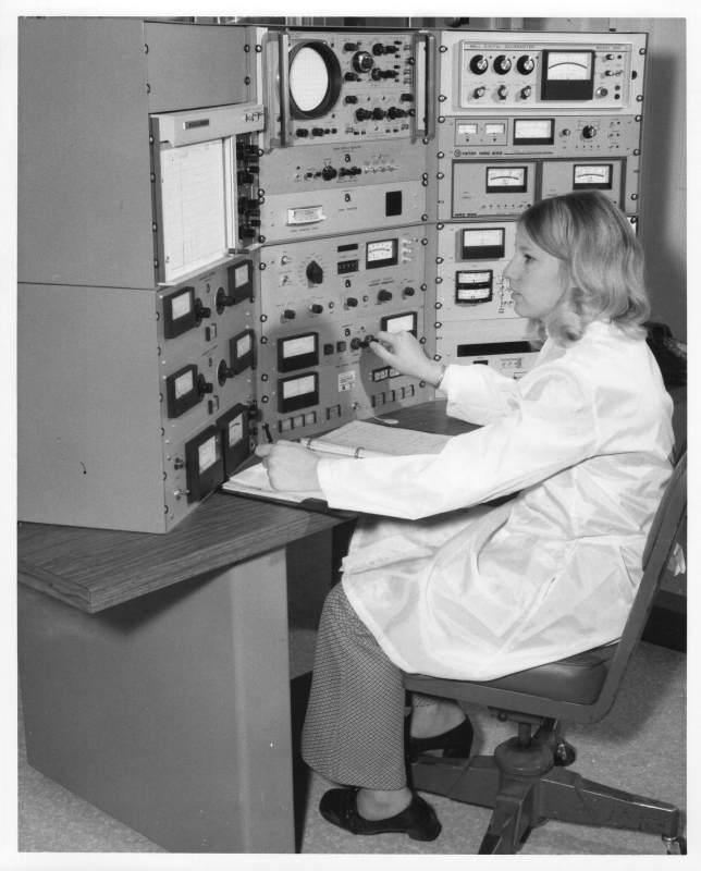
the separation magnet is behind her
and the wall behind her
is the lead-lined high voltage enclosure.

separation magnet behind gate valve
